Structural Simulation of the 7.2-Meter Radome Project
Introduction
Recently, our company received a project to design a 7.2-meter radome. The target frequency bands are primarily S and C bands. The main dimensions of the radome are as follows:
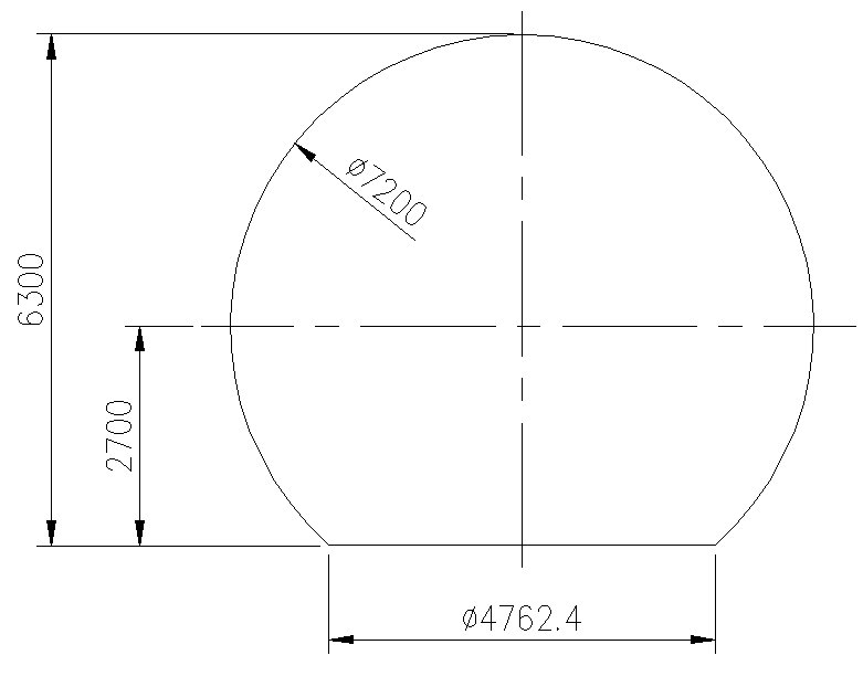
Figure 1: Radome Dimensions
Background and Objective
In the initial phase, we optimized the segmentation of the radome. As the structure is a critical aspect of the radome, wind load is the most significant structural load over the radome's lifespan. Due to the varying and relatively large dimensions of the radome, practical experiments are not suitable for validation. Therefore, structural simulation is typically employed to accelerate the design cycle.
Our objective is to conduct a wind load simulation to confirm the wind pressure distribution on the radome surface. The calculations assume a stable wind speed of 60 m/s. The following sections detail the specific process involved.
Simulation Process
1. Creating the Radome Simulation Model
The first step in the simulation process is creating a detailed model of the radome. This involves using computer-aided design (CAD) software to replicate the physical characteristics of the radome.
Purpose:
The simulation model serves as a virtual prototype, enabling engineers to conduct various analyses without the need for physical models. This saves time and resources and allows for rapid iteration and optimization.
Importance:
A precise simulation model is crucial for accurate results in subsequent analyses, such as structural integrity under wind load, material stress, and deformation.
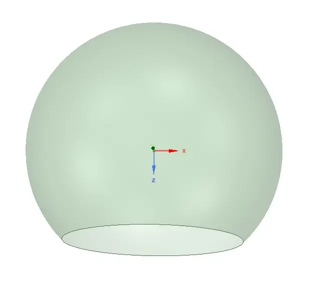
Figure 2: Radome Simulation Model
2. Establishing the Wind Tunnel Flow Field
The next step is to establish the wind tunnel flow field for simulating the aerodynamic environment around the radome.
Purpose:
Wind tunnels are essential for studying the effects of airflow around objects. By simulating these conditions, we can understand how the radome will behave under different wind conditions. This includes assessing the distribution of wind pressure and identifying potential points of structural stress.
Types of Wind Tunnels:
- Subsonic Wind Tunnels: Used for low-speed aerodynamic testing.
- Transonic Wind Tunnels: Suitable for speeds around the speed of sound.
- Supersonic and Hypersonic Wind Tunnels: Used for high-speed testing, such as in aerospace applications.
In our case, a subsonic wind tunnel is appropriate given the radome’s operational environment.
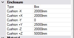
Figure 3: Wind Tunnel Flow Field Dimensions
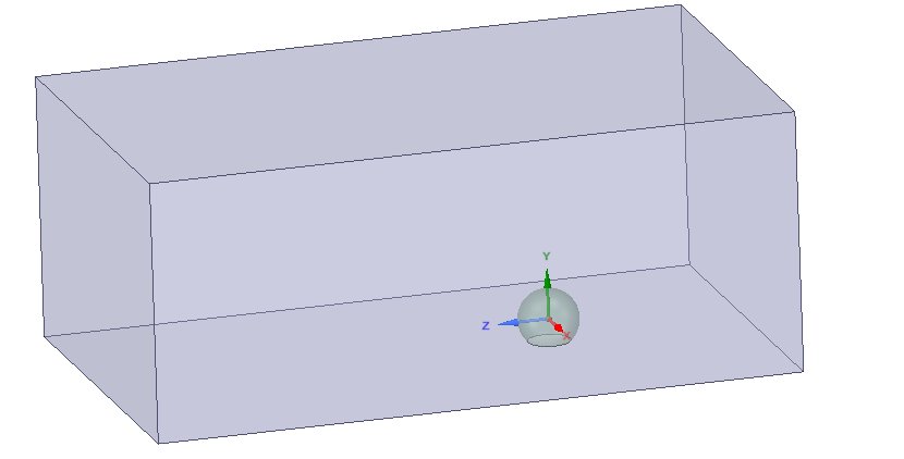
Figure 4: Wind Tunnel Flow Field Domain
3. Meshing the Flow Field
Meshing involves dividing the flow field into smaller, discrete elements called cells. This process is crucial for numerical simulations as it allows for the detailed analysis of fluid dynamics.
Purpose:
Meshing enables the computational fluid dynamics (CFD) software to solve complex equations governing fluid flow. The finer the mesh, the more accurate the simulation, although it also requires more computational power.
Process:
The flow field around the radome is divided into a grid where fluid properties like velocity, pressure, and turbulence are calculated.

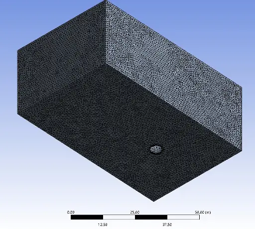
Figure 5: Flow Field Meshing
4. Running the Simulation with the K-ε Model
The K-ε (k-epsilon) turbulence model is used to simulate the airflow around the radome. This model is widely used in CFD for its balance between accuracy and computational efficiency.
Purpose:
The K-ε model helps predict the behavior of turbulent flow, which is critical for understanding how wind interacts with the radome.
Residual Curve:
This curve represents the convergence of the solution. A decreasing residual curve indicates that the simulation is approaching an accurate solution.
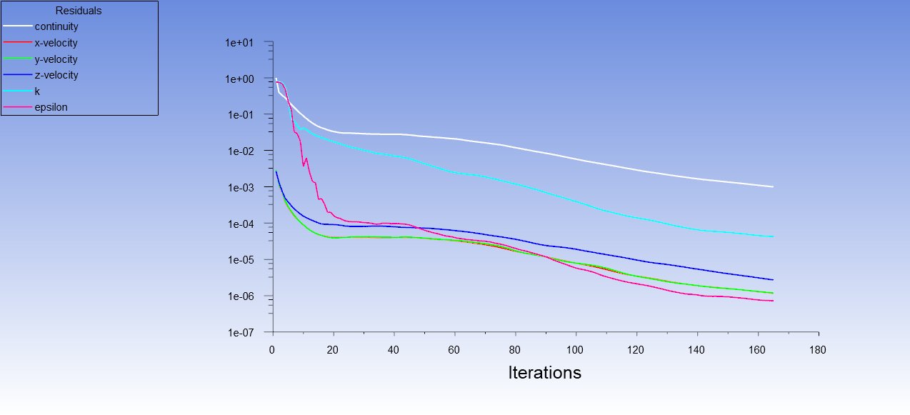
Figure 6: Residual Curve
5. Wind Speed Distribution
After running the simulation, we obtain the wind speed distribution around the radome. This shows how wind speed varies at different points on and around the radome.
Purpose:
Understanding wind speed distribution helps in identifying areas of high wind pressure and potential aerodynamic issues.
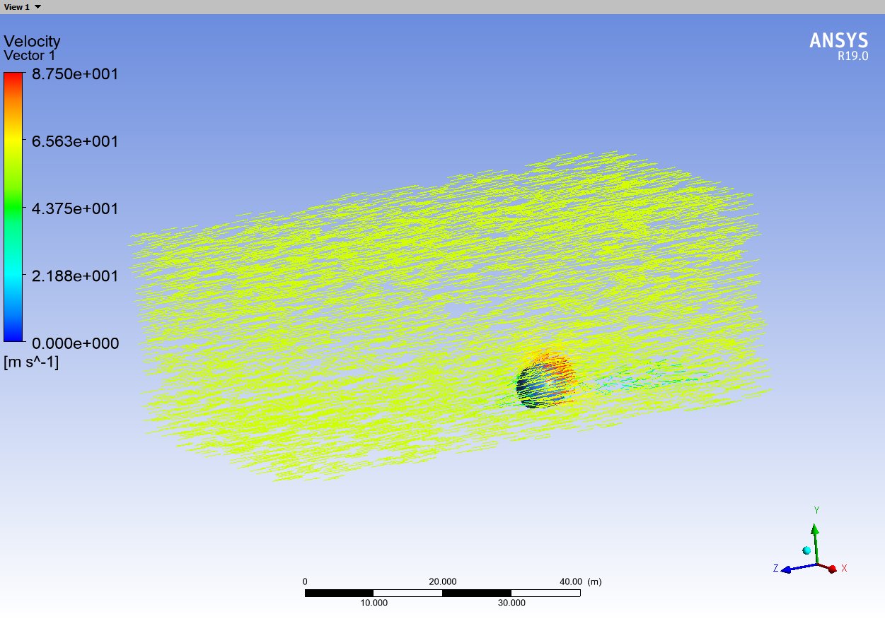
Figure 7: Wind Speed Distribution
6. Pressure Distribution on the Radome
The final step involves analyzing the pressure distribution on the radome surface. This is crucial for structural analysis.
Purpose:
Pressure distribution data is used to assess the radome's structural integrity, ensuring it can withstand operational and extreme weather conditions without failure.
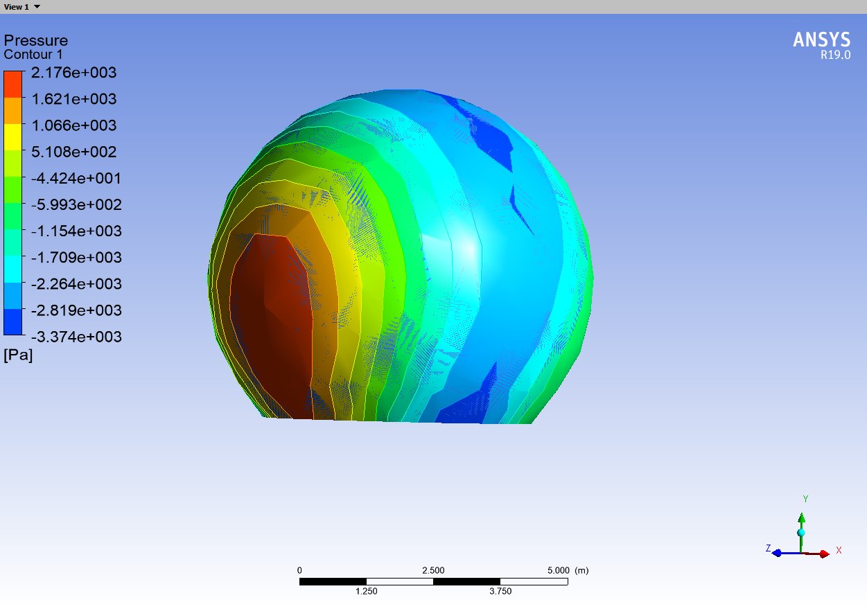
Figure 8: Radome Wind Pressure Distribution
Structural Analysis
Based on the wind pressure distribution, we will conduct strength, stiffness, and safety analyses of the radome. This includes ensuring the structure can withstand operational and extreme conditions, maintaining integrity and functionality throughout its lifespan.
Detailed Design Considerations
Material Selection:
The choice of materials for the radome is crucial. We need materials that offer a good balance between lightweight and high strength, such as advanced composites.
Manufacturing Process:
The manufacturing process should ensure minimal defects and high precision. Techniques such as automated fiber placement (AFP) or resin transfer molding (RTM) could be considered.
Environmental Factors:
The radome must be designed to withstand various environmental factors including temperature fluctuations, humidity, and UV radiation. Coatings and surface treatments can be applied to enhance durability.
Future Work
Our next steps involve comprehensive structural analysis and verification through additional simulations and, where feasible, physical testing of smaller scale models or components. We aim to finalize the design parameters to ensure the radome meets all operational requirements and performance standards.
Conclusion
The design and simulation of the 7.2-meter radome involve a meticulous process of modeling, simulation, and analysis. By leveraging advanced simulation tools and adhering to rigorous design standards, we aim to deliver a robust and reliable radome that meets the demands of modern communication technologies.
Tags: Radome Design, Structural Simulation, Wind Load Analysis, Composite Materials, Advanced Manufacturing, S/C Band Radome, Wind Tunnel Testing, Engineering Design, Telecommunications Infrastructure, Structural Integrity